Xlr To Trrs Wiring Diagram First Wiring
Pinouts > Audio / Video hardware connectors. 6 pin XLR female connector. Edit. Submit New. Application. Pin 1. Pin 2. Pin 3. Pin 4.
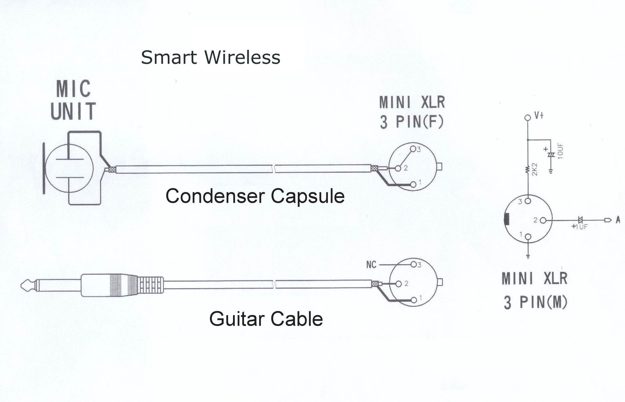
Sennheiser Receiver Xlr To Mini Cable Wiring Diagram
Pin 4. Notes. 12V generic power source. Ground. NC or Ground. NC or +12V. +12V. 11 to 18V range, widely used for broadcast equipment. Female on power source, male on device.
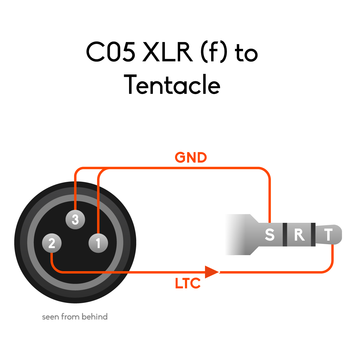
Pinouts and wiring diagrams for Tentacle cables Tentacle Sync
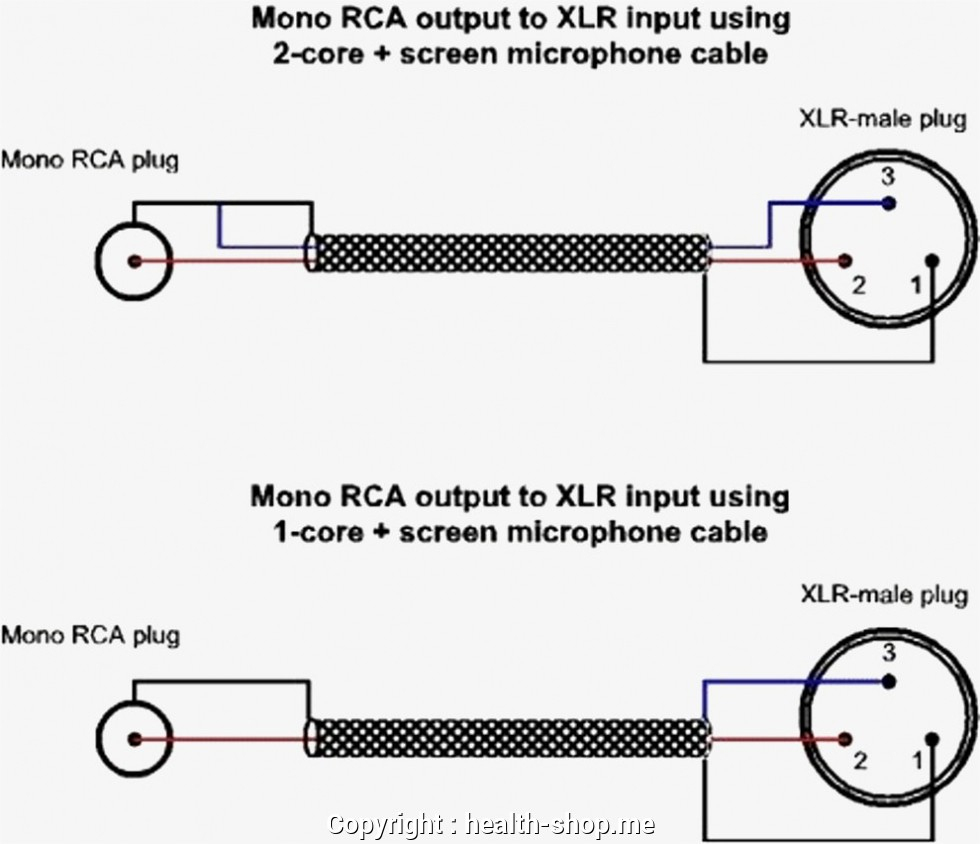
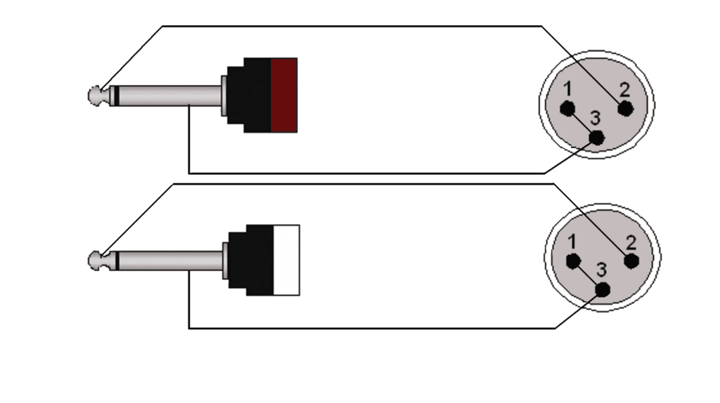
Volume Pot Wiring Diagram If you want the pot to turn in the opposite direction, pins 1 and 3 can be reversed. Be sure to always ground to the shell to avoid hum!. Connect the XLR's Pin 3 to the 1/4" Tip . Preamp Tubes - Improve The Sound Of Any Tube Guitar Amp In An Instant! Preamp tubes are rated in percentage of output. The higher the.

Mini Xlr Wiring 3 5mm Stereo Right Angle Mini Jack Male To 3 Pin Mini
Hot Plugging XLR 3-Pin Wiring - Male/Female Type How do XLR connections work? What is the XLR pinout on A series models? What do the pins mean in XLR? What is the use of 5-pin XLR? What is the pin 1 on the XLR? What is the voltage of the XLR pinout? Is XLR DC or AC? How many ohms is XLR cable?
Stereo Xlr Wiring Diagram Wiring Diagram
Building Info for Kwai Shing West Estate Block 5. Kwai Shing West Estate Block 5. Kwai Shing Circuit. Kwai Fong. Kwai Tsing District. New Territories. Year of Completion1975. Building Age48. Property TypeResidential.
How To Build Your Own Xlr Cables A Stepstep Guide Studio Diy Xlr
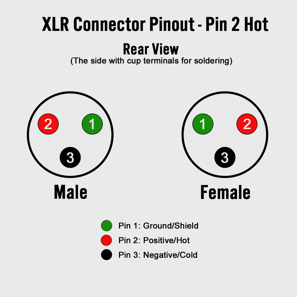
Assembly Instructions Shop Connectors Shop Cable 3-Pin XLR Audio Pinout Three-pin XLR connectors are by far the most common style, and are an industry standard for balanced audio signals. The pinout listed below is the Audio Engineering Society (AES) industry standard for balanced audio XLR wiring. Sony 4-Pin XLR D.C. Power Supply Pinout
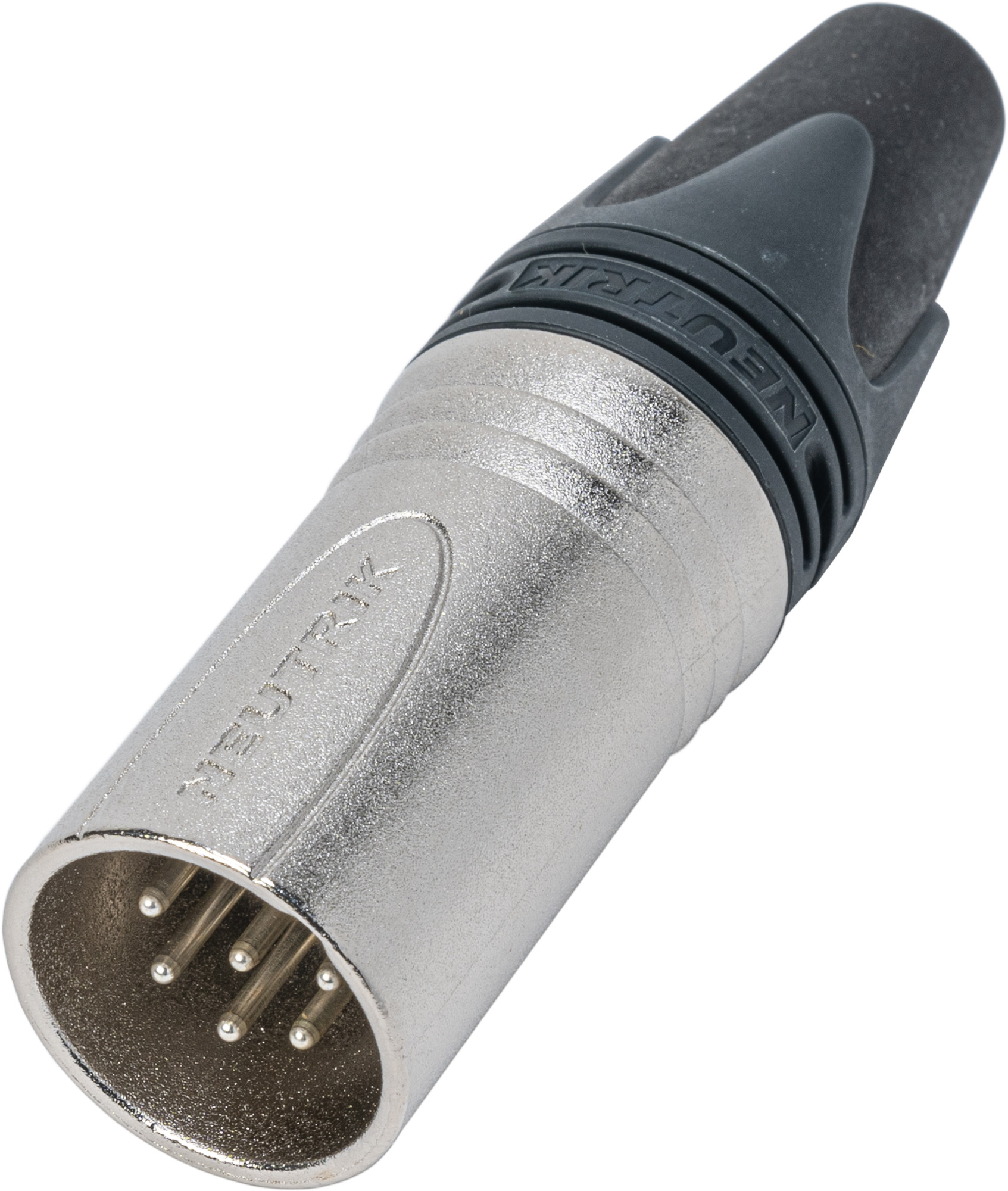
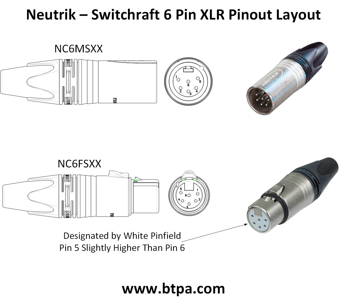
Neutrik NC6MSXX 6 Pole XLR Male Nickel/Silver Switchcraft Pin Layout
Layout: XLR 3 This is arguably the most common type of XLR connecor. It is used for balanced audio signals in microphones, mixers, amplifiers, etc.. Although 3-pin XLR is often used as a low-cost power connector, it is recommended to use 4-pin XLR instead, as its wiring scheme is unambiguous. The receptable that is fitted to the chassis of.
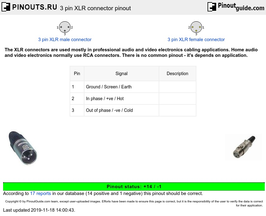
Professional audio / entertainment devices 3 pin XLR connector pinout
This is where the three pins of an XLR come into play. Of course, one pin is a ground reference. However, the other two pins are there to compensate for inevitable noise in the raw signal. This is the magical part. One pin sends the signal as is, and the other pin sends the signal with opposite polarity by referencing its voltage opposite to.
How To Build Your Own Xlr Cables A Stepstep Guide Studio Diy Xlr
Edit Submit New The XLR connectors are used mostly in professional audio and video electronics cabling applications. There is no common pinout - it's depends on application Reverse numbering?
Mini Xlr 4 Pin Wiring Diy Audio Electronics From Zynsonix Com
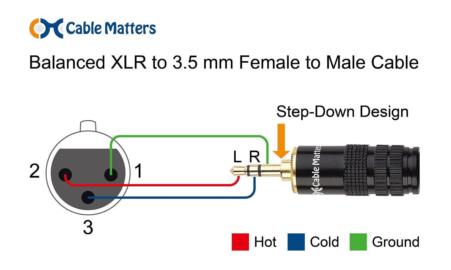
Pin 1 is usually connected to the ground or shield, pin 2 is the positive signal conductor, and pin 3 is the negative signal conductor. The wiring diagram shows the specific connections between these pins and the corresponding cable colors that are typically used in Mini XLR cables.

Kriscables USB, Aviator, Mini XLR Pinout Diagram kriscables
The three pin and five pin XLR pinout is a very standard connection used for audio (mic level & line level - 3 pin) and lighting control (DMX - 5-pin) applications. This article shows the XLR Pinout diagrams for both 3-pin and 5-pin connectors. You'll also discover each XLR pin's polarity. 3 Pin XLR Pinout
Standard Xlr Wiring Diagram Yamaha
Submit New The XLR connectors are used mostly in professional audio and video electronics cabling applications. Home audio and video electronics normally use RCA connectors. There is no common pinout - it's depends on application. Balanced Audio (3 pole XLR): Unbalanced Audio (3 pole XLR):

Female Xlr Wiring Diagram Organicent
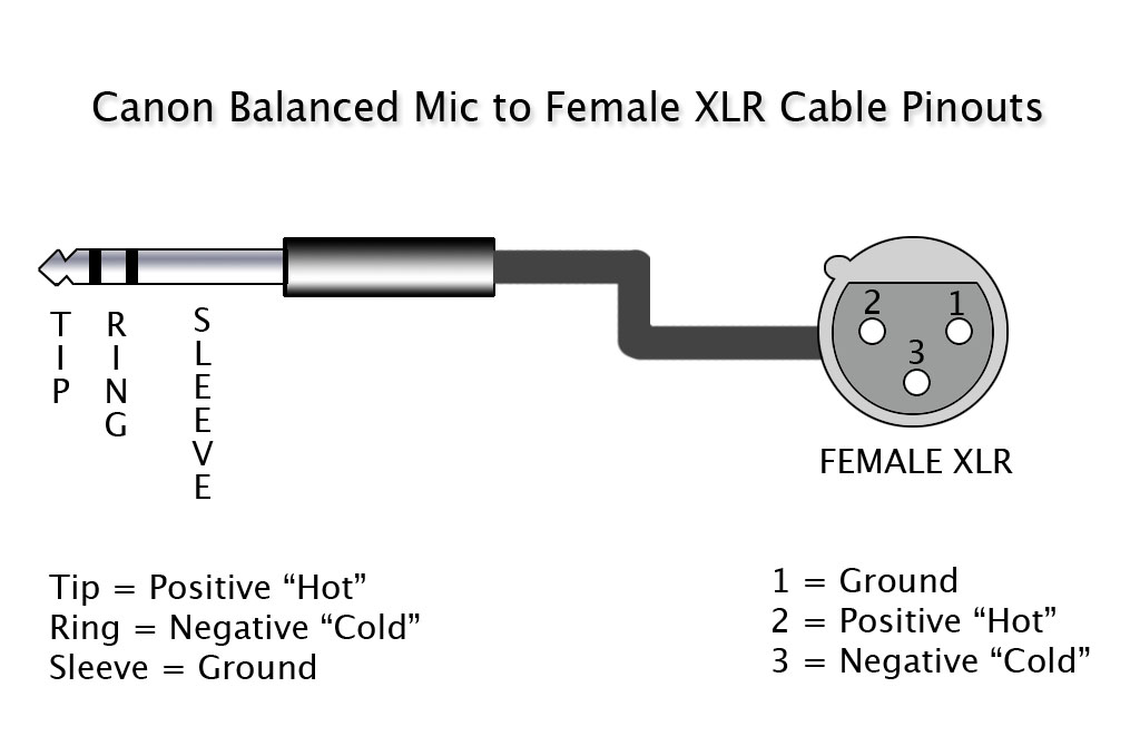
What are the electrical connections of the three pin jack (XLR) on the balanced version of a professional mic? Answer XLR pin 1 = shield; XLR pin 2 = audio +; XLR pin 3 = audio - Last Edit Date 1/29/2019

3.5mm To Xlr Wiring Diagram
December 23, 2022 by Kanishk Godiyal XLR is an electrical connector mainly used for cabling in audio and video applications. These connectors are also used in lighting control, low-voltage power supplies, etc. XLR connector was discovered by James H Cannon (the founder of Cannon Electric in Los Angeles).
BestTronics Mfg., Inc. > 4,5,6,7 Pin XLR > XLR6SCXX
The number of pins varies. As of 2016, XLR connectors are available with up to 10 pins, [5] and mini XLR connectors with up to eight. XLR connectors from different manufacturers will intermate, with the exception of six-pin models, which are available in two incompatible designs.

mini xlr wiring diagram Wiring Draw And Schematic
Step 1: Unscrew the plastic housing from the metal housing on the plug's end. See the pictures below for an illustration of where to twist. Step 2: Now, pull the plastic piece back with the protective sheath to reveal the inside. You will see a plastic guard that goes around the soldered pins.